Week 11 [Fri, Oct 22nd] - Topics
Guidance for the item(s) below:
As you will be updating documentation of your project soon, here are some guidelines to help you with that.
Guidance for the item(s) below:
Software engineers often have to write developer documentation to explain their work to others. One important objective of developer documentation is to explain the design and the implementation of the software, which usually uses diagrams as models of the design being described.
Let's learn what models are, and how they are useful even beyond mere documentation.
Guidance for the item(s) below:
Lets' refresh our memory about Class/Objet Diagrams, starting with the basics.
Can explain structure modeling of OO solutions
An OO solution is basically a network of objects interacting with each other. Therefore, it is useful to be able to model how the relevant objects are 'networked' together inside a software i.e. how the objects are connected together.
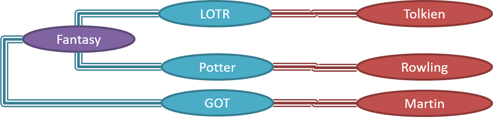
Given below is an illustration of some objects and how they are connected together. Note: the diagram uses an ad-hoc notation.

Note that these object structures within the same software can change over time.
Given below is how the object structure in the previous example could have looked like at a different time.
However, object structures do not change at random; they change based on a set of rules, as was decided by the designer of that software. Those rules that object structures need to follow can be illustrated as a class structure i.e. a structure that exists among the relevant classes.
Here is a class structure (drawn using an ad-hoc notation) that matches the object structures given in the previous two examples. For example, note how this class structure does not allow any connection between Genre objects and Author objects, a rule followed by the two object structures above.

UML Object Diagrams are used to model object structures and UML Class Diagrams are used to model class structures of an OO solution.
Here is an object diagram for the above example:

And here is the class diagram for it:

Can use basic-level class diagrams
Contents of the panels given below belong to a different chapter; they have been embedded here for convenience and are collapsed by default to avoid content duplication in the printed version.
Classes form the basis of class diagrams.
Associations are the main connections among the classes in a class diagram.
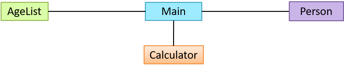
The most basic class diagram is a bunch of classes with some solid lines among them to represent associations, such as this one.
An example class diagram showing associations between classes.
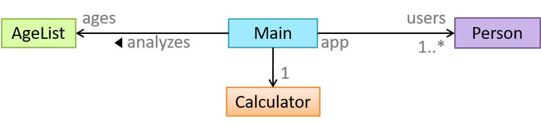
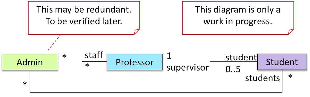
In addition, associations can show additional decorations such as association labels, association roles, multiplicity and navigability to add more information to a class diagram.
Here is the same class diagram shown earlier but with some additional information included:
Can distinguish between class diagrams and object diagrams
Compared to the notation for class diagrams, object diagrams differ in the following ways:
- Show objects instead of classes:
- Instance name may be shown
- There is a
:before the class name - Instance and class names are underlined
- Methods are omitted
- Multiplicities are omitted
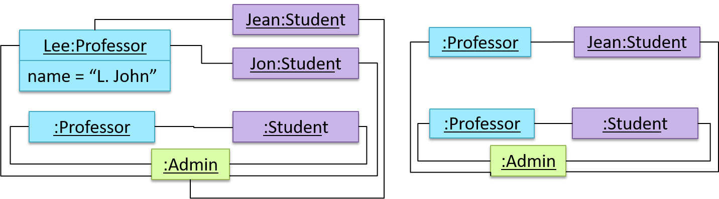
Furthermore, multiple object diagrams can correspond to a single class diagram.
Both object diagrams are derived from the same class diagram shown earlier. In other words, each of these object diagrams shows ‘an instance of’ the same class diagram.
Can show an association as an attribute
An association can be shown as an attribute instead of a line.
Association multiplicities and the default value can be shown as part of the attribute using the following notation. Both are optional.
name: type [multiplicity] = default value
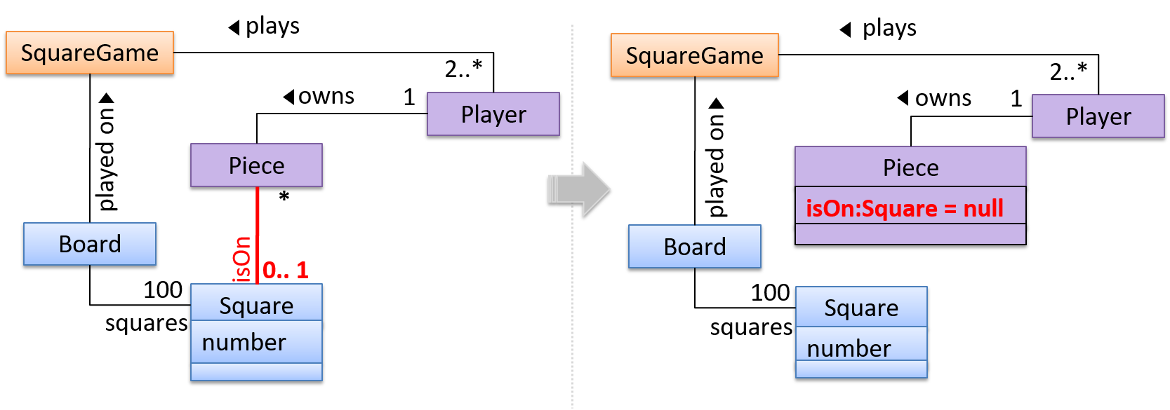
The diagram below depicts a multi-player Square Game being played on a board comprising of 100 squares. Each of the squares may be occupied with any number of pieces, each belonging to a certain player.
A Piece may or may not be on a Square. Note how that association can be replaced by an isOn attribute of the Piece class. The isOn attribute can either be null or hold a reference to a Square object, matching the 0..1 multiplicity of the association it replaces. The default value is null.
The association that a Board has 100 Squares can be shown in either of these two ways:
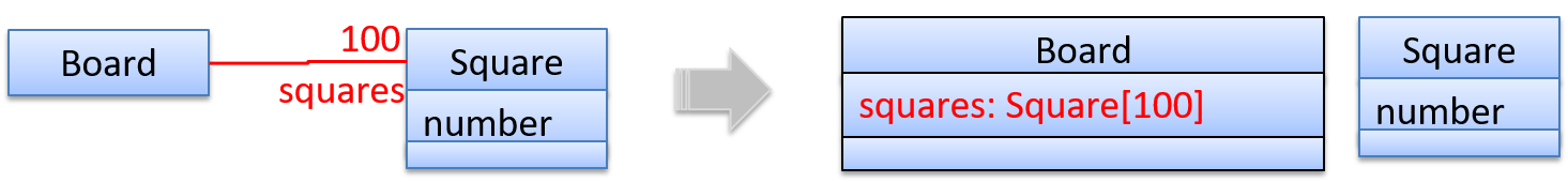
Show each association as either an attribute or a line but not both. A line is preferred as it is easier to spot.
Follow up notes for the item(s) above:
Here is a worked examples covering the drawing of class/object diagrams using the basic notations:
Guidance for the item(s) below:
Having learned class/object diagrams basics, we can now move on to some intermediate CD/OD notations.
Follow up notes for the item(s) above:
Now, you can try these worked examples: